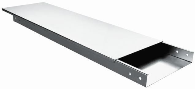
Raceway / Solid-bottom Cable Tray
Raceway / Solid-bottom Cable trays for fiber-optic cable installations where drooping of cables may affect system performance, solid-bottom (non-ventilated) cable trays are preferred.
However, the main reason for selecting solid-bottom trays is a concern for electromagnetic/ radio-frequency interference protection.
Product Specification
| Tray Width (W) | Tray Height (H) | Tray Collar (C) | Thickness (T) | Tray of Raw Material | Finish |
| 50 mm or 1000 mm | 25 mm to 100 mm | 15 mm to 25 mm | 1.6 mm to 3.00 mm | Mild Steel (M.S) & Aluminium & S. S |
Hot Dip Galvanized Powder Coated Enamel Painted |
Raceways
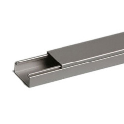
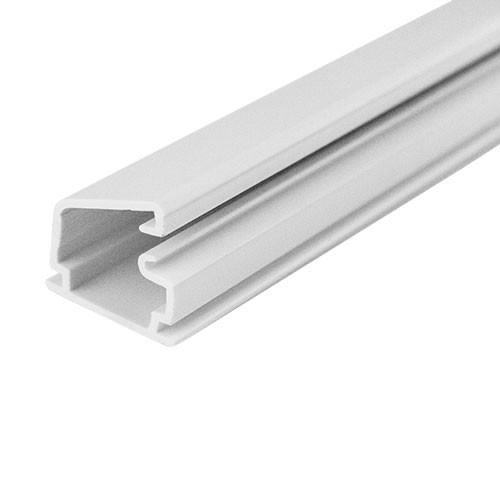
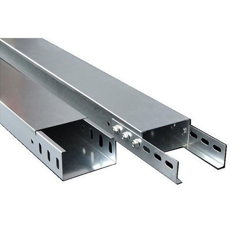
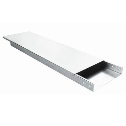
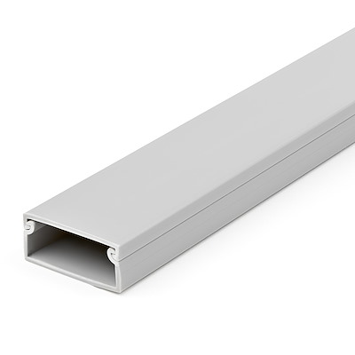
Fiber-optic cable installations frequently go with solid-bottom cable trays because the drooping of fiber-optic cables may degrade system performance. However, the main argument for selecting solid-bottom trays is to reduce electromagnetic/radio-frequency interference or for sensitive circuitry.
When the equipment room serves both computer and telecommunications equipment, under-floor cable-tray systems frequently get installed. Single unjacketed conductors and splices are permitted in cable trays. And the NEC says cable tray is permitted for service conductors, feeders, branch circuits, communications circuits, control circuits, and signaling circuits. These requirements as well as Uses Permitted and Uses Not Permitted as well as other specifications and construction and installation details are included in NEC Article 392.
Installation Process –
- Generally used for minimal heat generating electrical or telecommunication applications with a short to intermediate support span of 5 to 12 feet.
- The main reason for selecting a solid bottom cable tray (with covers) is the concern of EMI/ RFI shielding protection for very sensitive circuits. A solid bottom steel cable tray with steel covers provides a good degree of shielding if there are no breaks or holes in the completed installation.
- The solid bottom cable tray system has a disadvantage in that moisture can build up in the cable trays. This can be controlled by drilling 1/4 inch drain holes in the bottom of the cable tray at three-foot intervals (at the middle and very near the sides) if the cable tray is not being used for EMI/RFI shielding.
- Some engineers and designers specify solid bottom cable trays (often with covers) in the belief that all electrical circuits have to be totally enclosed by metal. The cable trays are just supporting cables that are designed for such installations. Cable failures in cable tray run rarely happen. Cable failures due to cable support problems in cable trays are nonexistent.
