Cable Trays are the exoskeleton of any modern infrastructure. Cable Tray is applied across all industry verticals like Power, Oil & Gas, Steel, Sugar, Chemical & Fertilizer, Solar, Residential & Commercial infrastructure, etc.
It is increasingly common to see a large amount of data and communication cabling with bandwidth and throughput demands squeezed into a limited area. All of this may require robust air conditioning to control the I2R temperature rise, not to mention clean electric heat and ventilation where precise temperature control is a factor.
The cable tray is a wonderfully efficient tool used to manage all these wires. With a grounded metal barrier along the centerline to separate power wiring and data/communication cabling, a single, large installation is capable of routing a large amount of wiring. It heads off the possibility of a disorganized mass of conductors that are difficult to trace when changes must be made or faults located.
A point to note is that there is a difference between cable trays and raceways. The NEC says a this system is a unit or assembly of units or sections and associated fittings forming a structural system used to securely fasten or support cables and raceways. That said, raceways generally mount on a wall in a room where power and communications cables are terminated. These are usually overhead or under raised floors but carry open wiring. They are used to distribute cables from the source to the point of use.
Cable Trays – Purpose & Advantages
Cable tray systems are alternatives to wire ways and electrical conduit, which completely enclose cables.
These are capable of supporting all types of wiring such as – High Voltage Power Lines, Power Distribution Cables, Control cables, Telecommunication cables, Fiber Optical Cables.
Purpose:
Cable trays are components of support systems for power and communications cables and wires. This system supports and protects both power and signal cables and facilitates upgrading, expanding, reconfiguring, or relocating networks.
Most of the These systems are open, allowing efficient heat dissipation and easy access for replacement and repairs. Although typically suspended from ceilings or affixed to walls, some these systems are suitable for under floor use.
Types of Cable Trays:
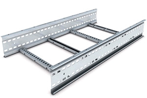
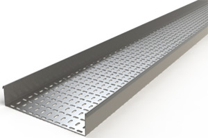
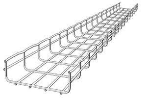
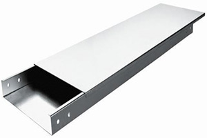
The following are popular cable tray types.
- Ladder-type
- Perforated type
- Raceway / Solid bottom type
- Wire mesh
An engineer or designer will usually specify the type of cable tray that has the features to suit the project. It depends on the situation and the environment.
The selection of cable tray depends upon the number of cables, size, spacing, and weight of cable in the tray.
Cable Tray Systems refer to Cable trays, Fittings and its accessories to connect the fittings & components.
Types of Cable Tray Fittings
- Straight Tray (Standard Length is 3 meter)
- Bend ( Used for Directional change in the horizontal plane – turns the route right or left)
- Elbow/riser (Used for directional change in the vertical direction – turns up or down)
- Tee (Used to take a new branch from the existing route)
- Reducer (To modify the width of cable tray systems based on cable runs)
- Cross (It’s similar to four road junction, which allows the intersection of two tray routes)
- Splice Plates (used to connect two individual fittings)
- Adjustable splice plates (purpose is similar to hinges indoors, we can adjust the angle as required while connecting the two fittings)
- Nuts & Bolts (Used to connect two fittings)
Other Factors those are inevitable in cable tray routings:
- Bending Radius of BEND, ELBO, TEE, CROSS
- Tray Height
- Equal or Unequal tee & cross
- Angle for bend & elbow (30,45,60,90 – standard angle)
- Supporting & Installation of Cable Trays.
- Load / Weight capability per meter length.
- Cable tray loading & cross-section list.
Finishing of Cable Tray
(1) Galvanized Coatings
- The most widely used coating for cable tray is galvanizing. It is cost-effective, protects against a wide variety of environ mental chemicals, and is self-healing if an area becomes unprotected through cuts or scratches.
- Steel is coated with zinc through electrolysis by dipping steel into a bath of zinc salts. A combination of carbonates, hydroxides and zinc oxides forms a protective film to protect the zinc itself. Resistance to corrosion is directly related to the thickness of the coating and the harshness of the environ ment.
(2) Pre-Galvanized:
- Pre-galvanized, also known as mill-galvanized or hot dip mill-galvanized, is produced in a rolling mill by passing steel coils through molten zinc. These coils are then slit to size and fabricated.
- Neighboring zinc protects areas not normally coated during fabrication, such as cuts and welds,. During welding, a small area directly affected by heat is also left bare, but the same self-healing process occurs.
- G90 requires a coating of .90 ounces of zinc per square foot of steel, or .32 ounces per square foot on each side of the metal sheet. In accordance with A653/A653M-06a, pre-galvanized steel is not generally recommended for outdoor use or in industrial environments.
(3) Hot-Dip Galvanized:
- After manufacturing and assembled, the entire tray is immersed in a bath of molten zinc, resulting in a coating of all surfaces.
- The length of time each part is immersed in the bath and the speed of removal determines Coating thickness. Hot dip galvanizing after fabrication creates a much thicker coating than the pre-galvanized process, a minimum of 3.0 ounces per square foot of steel or 1.50 ounces per square foot on each side of the sheet (according to ASTMA123,grade 65).
- The process is recommended for cable tray used in most outdoor environments and many harsh industrial environment applications.


